
Bias Lighting
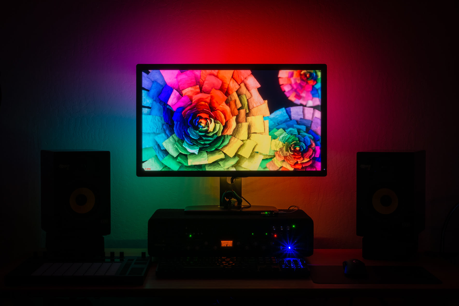
Recently, I’ve been on a small quest to upgrade my home lighting and in doing so started noticing all the less-than-cozy spots to try to fill with light. One of those dark spots was my computer desk, which doesn’t really have a good place to put a regular lamp. This was a good opportunity to add some bias lighting to brighten the wall behind my monitor.
Bias lighting is essentially a fancy term for lighting up the surroundings behind a display, which makes it less harsh to look at in a dark room. This is typically achieved with RGB LED strips that mirror what’s displayed on the edges of the screen. Luckily, I already had some laying around and the schematics and software for this are freely available.
I followed the excellent Parts Not Included DIY Ambilight with WB2812B LEDs guide for the majority of this project. Big props and credit to the author! As such, this is not meant to really be my own project guide, but more of a postmortem.
Since just following instructions is a bit boring, I took the opportunity to learn how to make my own simple PCB for the LED controller.
Overview
There are three main parts to this project:
- LED strip, with individually colored LEDs, attached to the back of the monitor
- LED controller, which drives the LED strip
- Software that captures the display output and sends it to the controller
LED strips
I used a generic 60 LEDs/meter WS2812B LED strip from AliExpress. These strips are several meters long, so they have to be cut down and soldered to fit around the monitor. I measured the monitor and a bit of Illustrator-ing later, was able to fit a total of 102 LEDs:
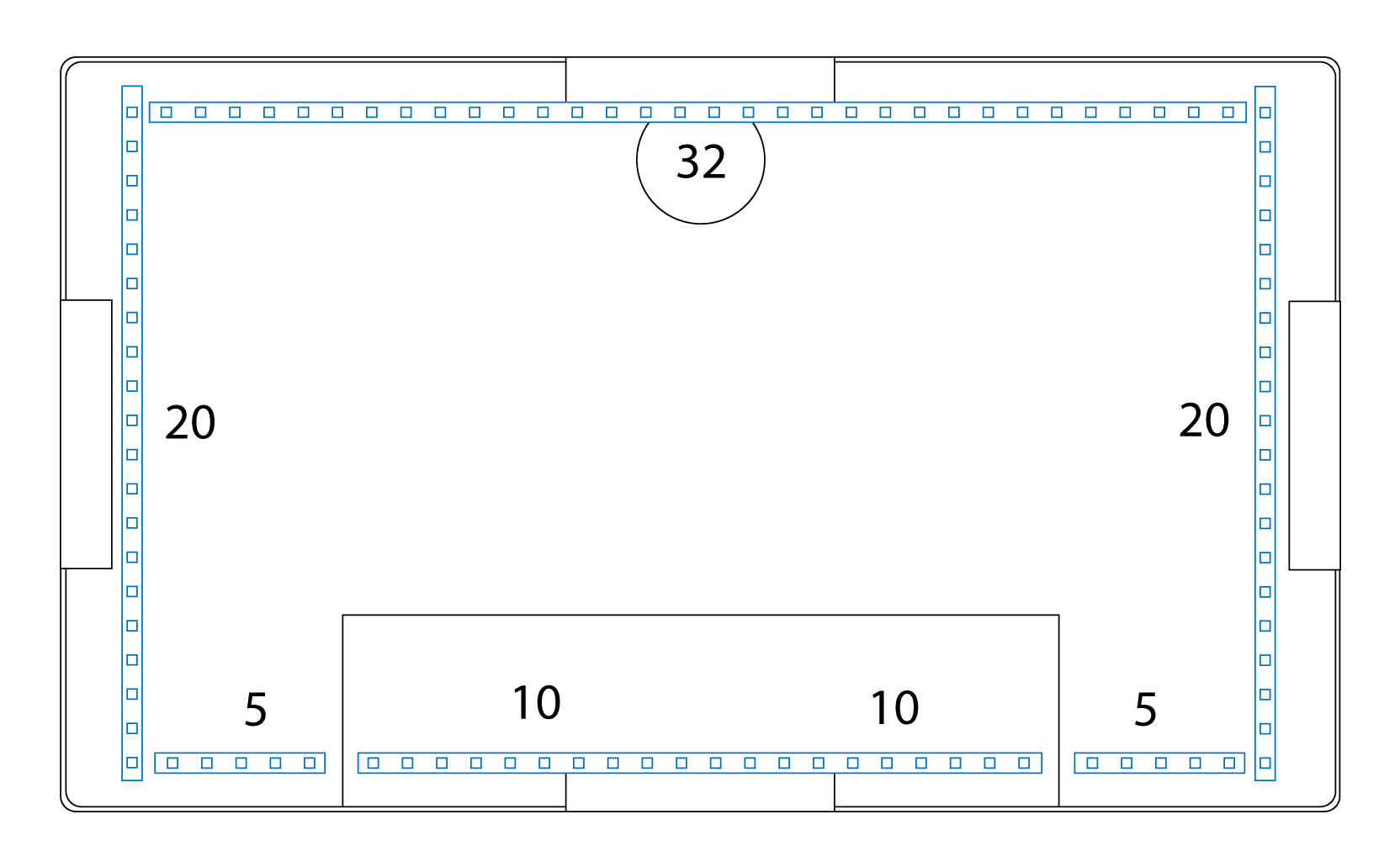
Planning the LED strip layout
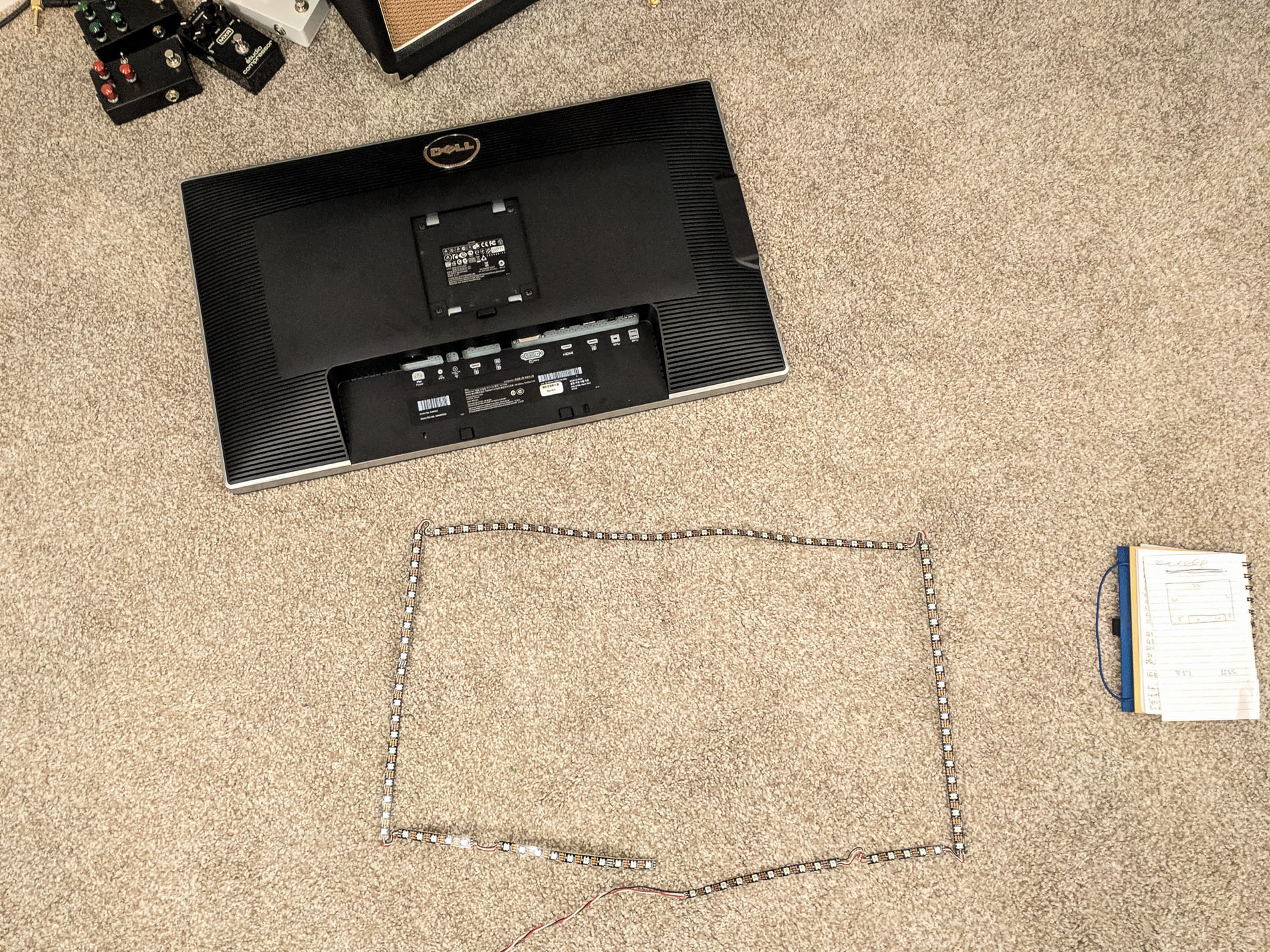
LED strip soldered and ready to stick to monitor
Unfortunately the adhesive on my strip was either too old (the strip was in storage for two years), or more likely, just not very good, so kept getting unglued – the ribbed surface on the monitor certainly didn’t help. I was able to get it to stick it a better by carefully heating it up with a heat gun.
Controller
The controller is based on an Arduino Nano, with just a few extra components to connect it to the LED strip and provide power. I used the open-source KiCad electronics design software to create the schematic and circuit board. The schematic is identical to the one from the AdaFruit NeoPixel guide.
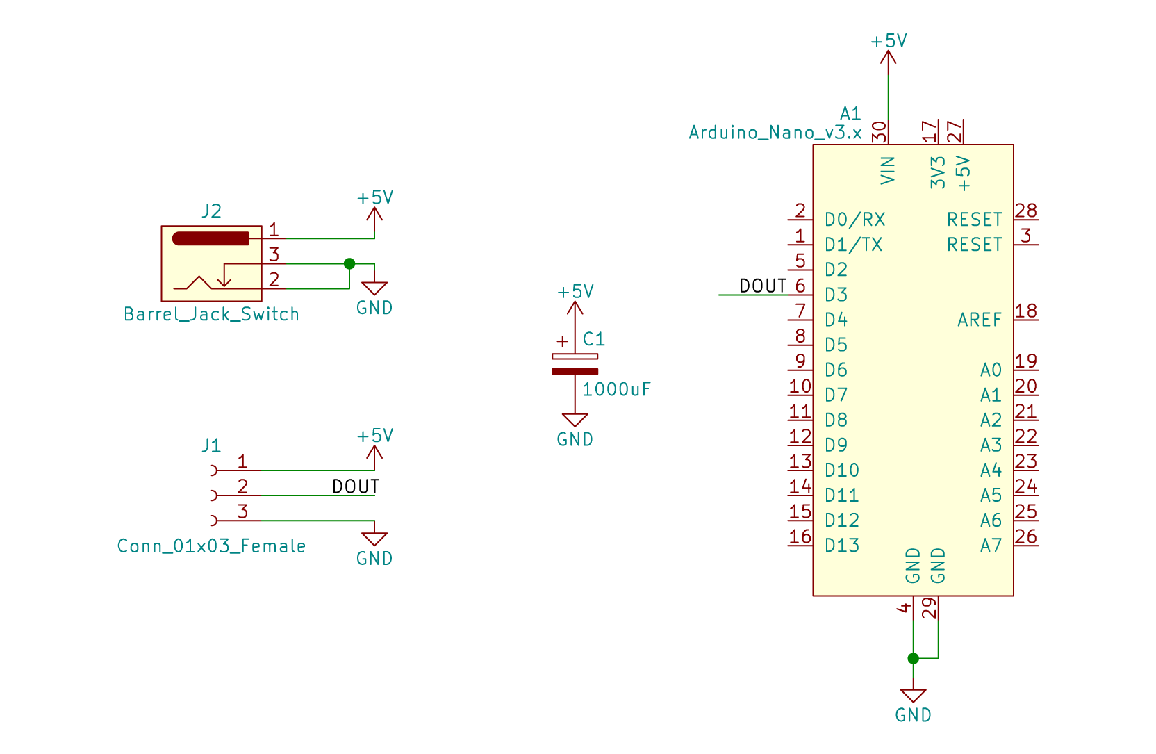
Schematic
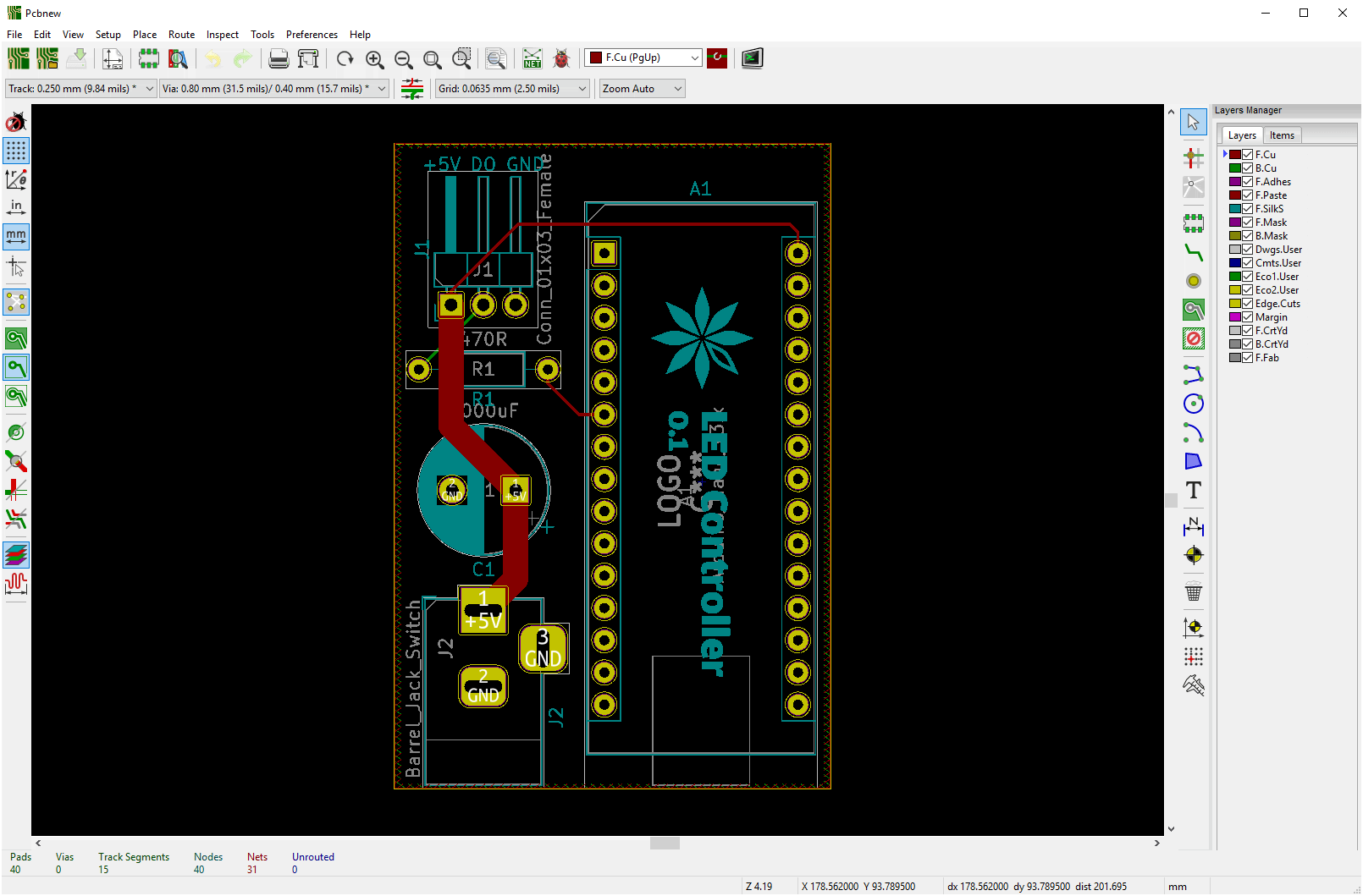
KiCad PCB editor

KiCad 3D rendered PCB
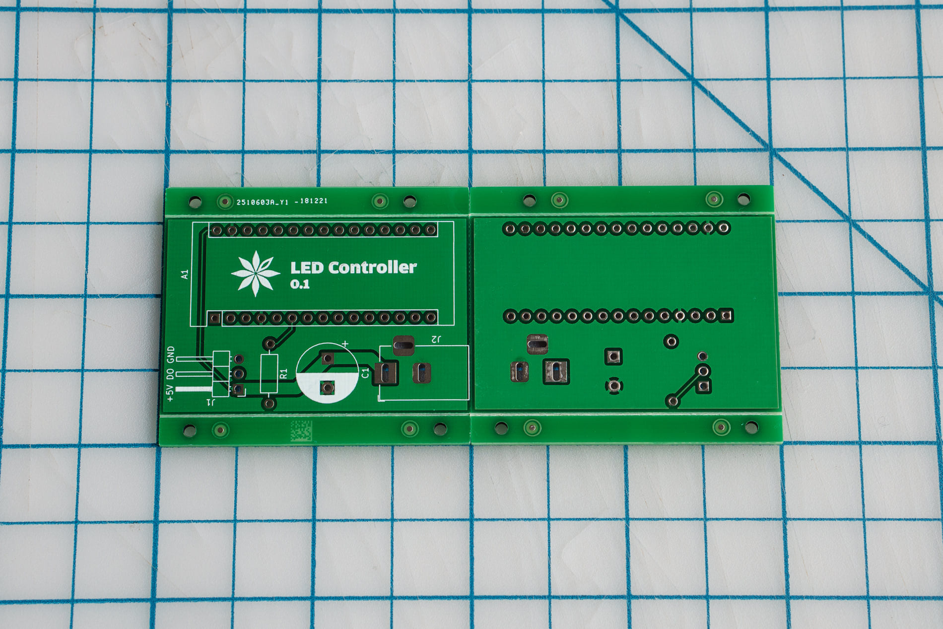
PCBs, ready to solder

Finished controller board
Software
The LED controller runs the the Adalight-FastLED Arduino sketch, modified to use the proper LED count (102) and data pin (D3). I also increased the serial baud rate from 115,200 to 250,000 baud to allow the strip to update at up to 60 Hz, as fast as my monitor.
My computer runs Prismatik which captures the display output and sends it to the controller over serial. The Arduino Nano on the controller has a USB-to-serial adapter onboard, so it plugs into the PC over USB and just works.
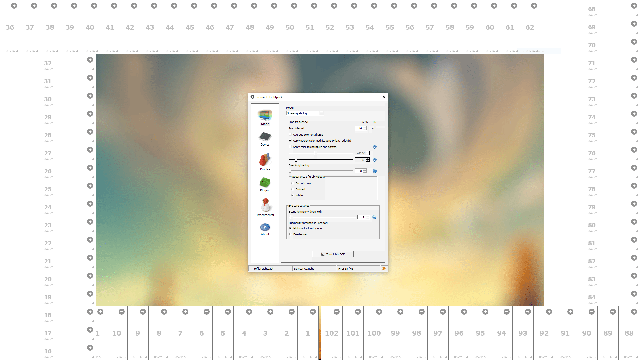
LED layout in Prismatik
Up next
There are definitely things I could improve on the PCB layout:
- The capacitor
C1could be rotated 180° to avoid the trace zig-zagging - The trace on the back of the board between
R1andDOUTis a bit too close to the+5Vpad
I’d also like to make a case for the project. A 3D printed one would be pretty interesting since I haven’t tried doing any 3D CAD or printing yet.