
Let’s Make: Headphone Adapter

Recently I acquired a pair of in-ear monitors (IEMs). They sound great, but are rather sensitive (105 dB/mW), so there’s a noticeable hiss when connected to my audio interface, even with the volume turned all the way down. It doesn’t take much amp power to drive these earphones, so the volume control has a limited range – it gets uncomfortably loud at only about a third up.
Luckily, after a bit of searching around, I found an awesome guide from DIY Audio Heaven that explains the problem and provides a design for an adapter that reduces overall volume, eliminating noise. The electronics are simple – a voltage divider with a few resistors – but the craft may not be, especially if you haven’t built audio cables before.
So, let’s make one!
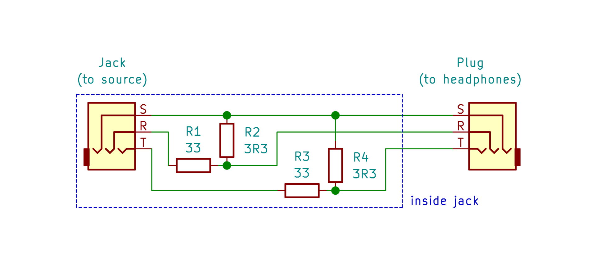
Circuit diagram

You’ll need this stuff
Let’s start with the ingredients:
- 3.5 mm stereo plug
- 3.5 mm stereo jack
- 26 AWG wire
- 3/8 in cable sleeving (e.g. Techflex Clean Cut)
- 2× 33Ω 1/8 W resistors
- 2× 3.3Ω 1/8 W resistors
- Black/clear heat shrink
- Electrical tape (e.g. Kapton)
- A soldering iron, solder
- Pliers, wire cutters, craft knife
- Heat gun, or lighter (a stovetop works too), for heatshrink
- Multimeter, for continuity testing
- Fabric samples, for a ridiculous photo background
(product links are unaffiliated; it’s just what I used)

Cable sleeving and equally-sized pieces of wire
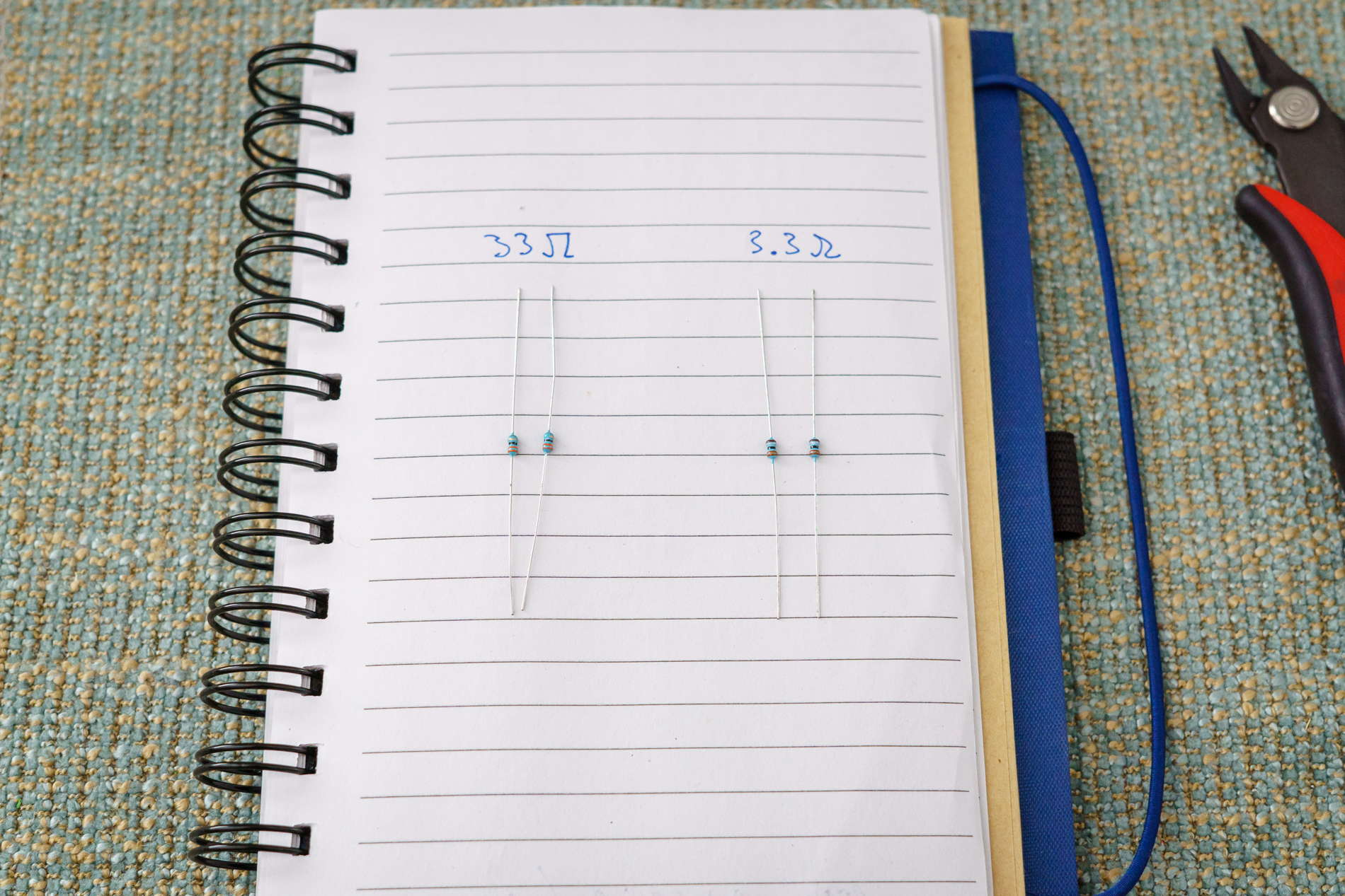
Two 33Ω 1/8 W resistors, two 3.3Ω 1/8 W resistors
You can use different values – when I was prototyping this, I only had 15Ω and 1.5Ω on hand, and that worked just fine (see Rick Chinn’s All About Pads for theory).
Make sure to use 1/8 W resistors, though, not the more common 1/4 W, since the latter won’t fit into the plug. I used 1% metal-film resistors because, why not, they were dirt cheap.
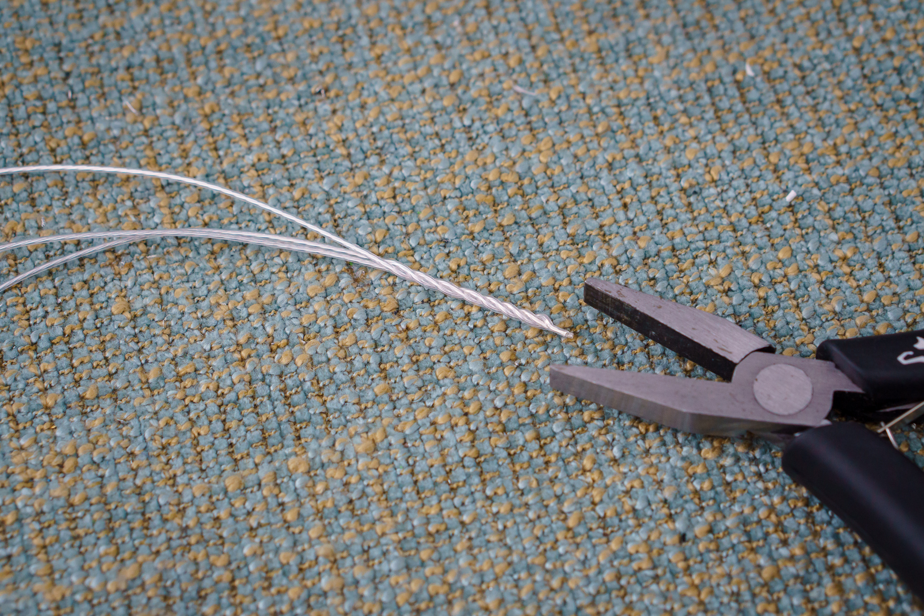
Twist your wire
Cut the wire into three equally sized lengths, about 4 in (10 cm), grab the ends with pliers, and twist together. For longer pieces of wire, you can use a hand drill.
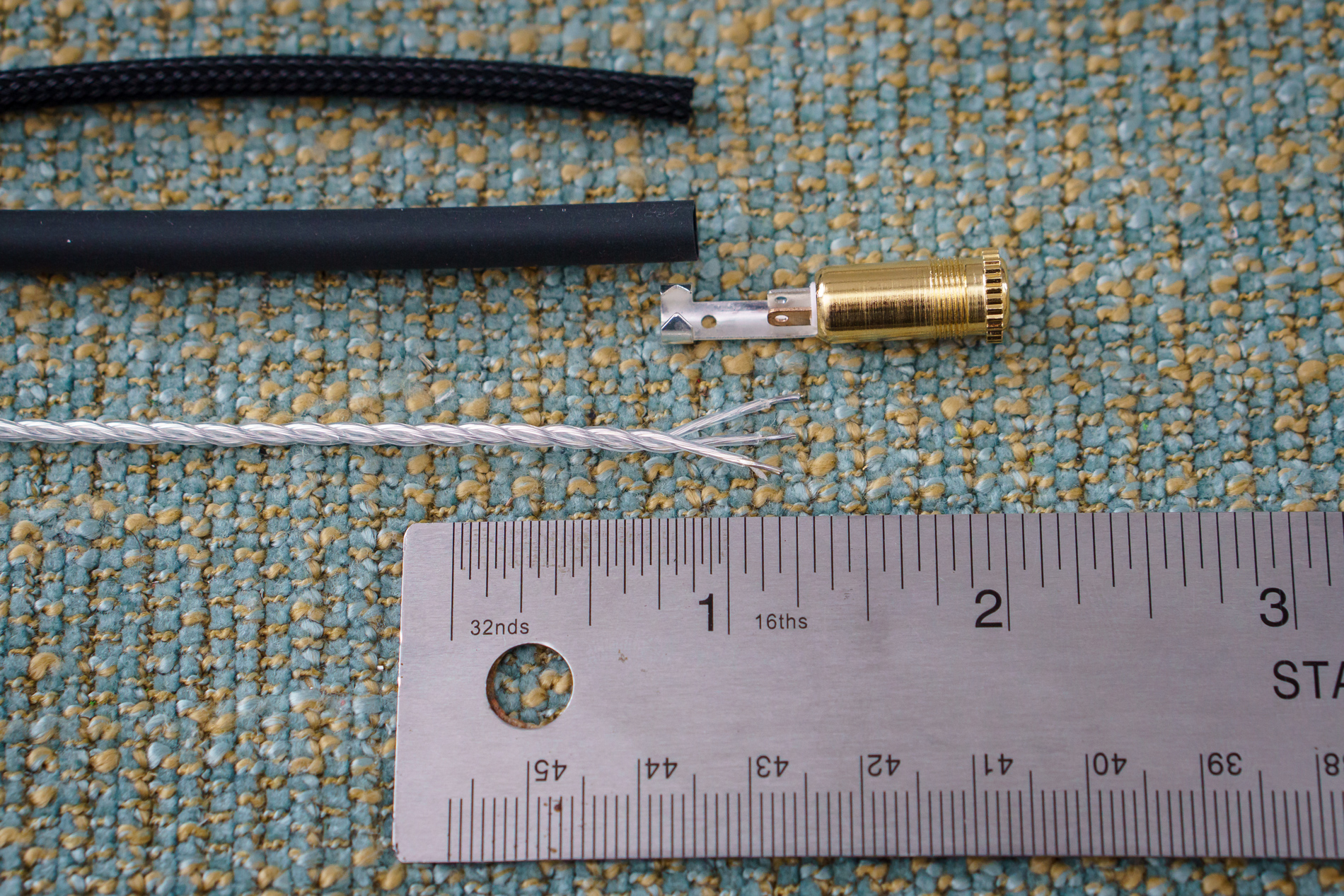
Strip the ends
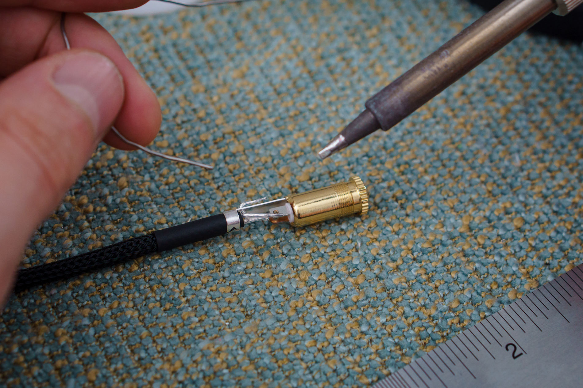
Add sleeving and heatshrink, then solder
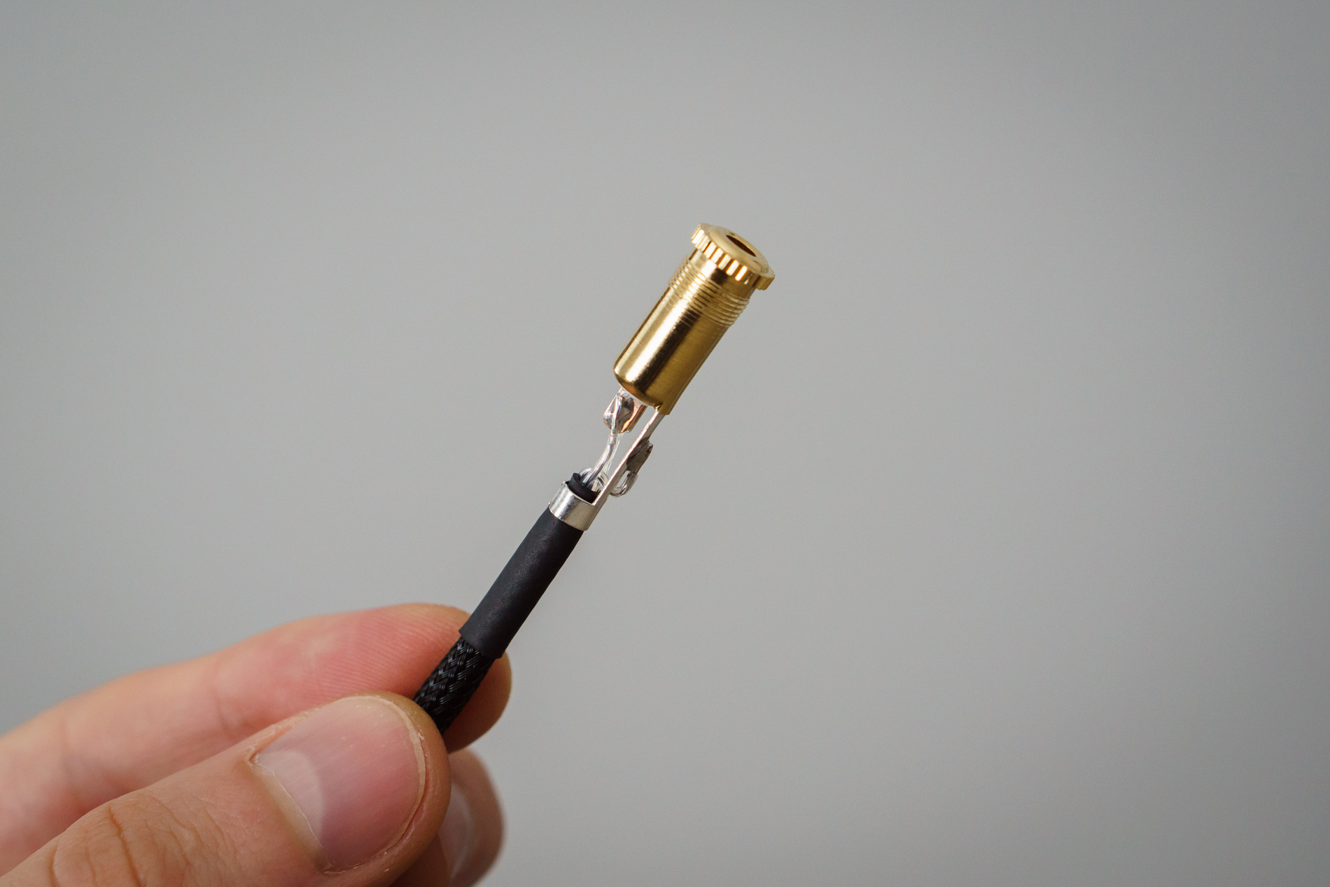
Jack complete

Solder 33Ω resistors into the plug
The jack houses the attenuation circuit, starting with the two 33Ω resistors (R1 and R3) soldered to the
tip and ring of the jack, and tucked away underneath. Make sure to add a bit of heatshrink to the
resistor connected to tip (on the left in the photo) to prevent its lead from touching the ring contact.
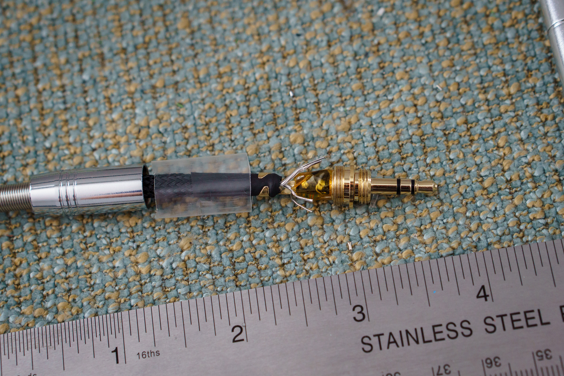
Join the cable and jack
Put the plug housing on the cable, an inch of heatshrink, and some clear heatshrink (in next photo), and crimp the jack on. Don’t forget to put all of these on before crimping – I forgot the clear heatshrink and had to stretch it over the jack.
Cover the resistors with some tape or an extra layer of heatshrink. I used some (off-brand) Kapton for flair.
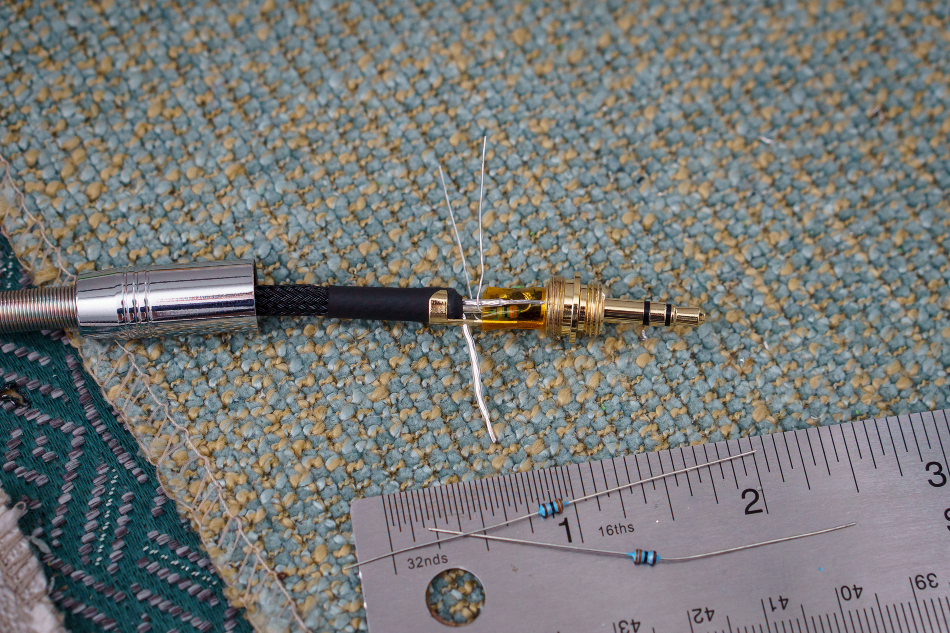
Match wires with resistor leads, and trim
Match the tip/ring wires with the tip/ring resistor leads, with a multimeter in continuity mode. I verified by connecting a 3.5mm extension cable (actually a spare plug) into the jack and probing between the tip and each wire. The outermost contact with the crimp is sleeve/ground.

Solder the 3.3Ω resistors
Solder one lead of each 3.3Ω resistors (R2 and R4) to ground, on the sleeve crimp contact.
Be quick when soldering the ground connection to avoid burning the heatshrink and sleeving underneath.
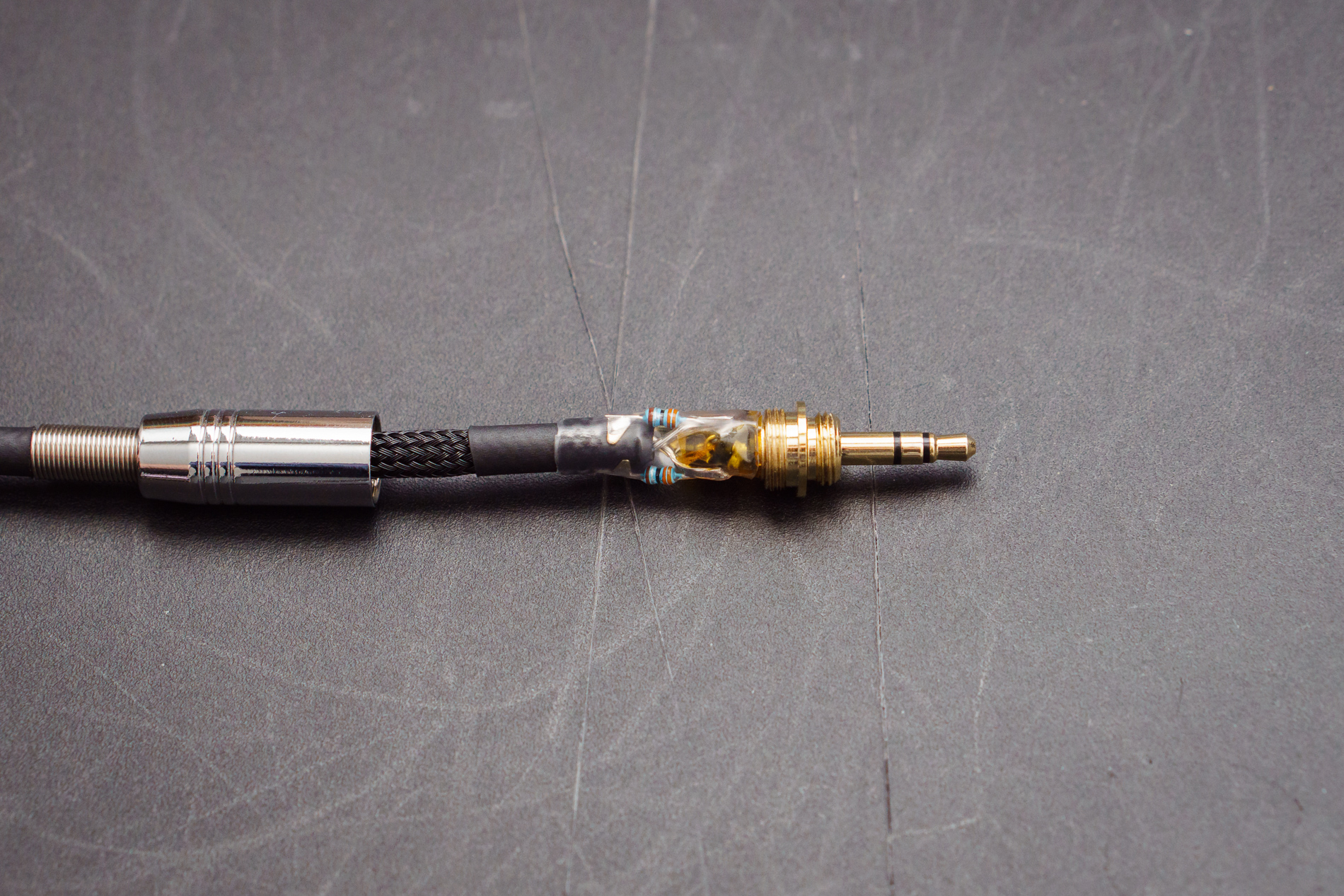
Solder and heatshrink
Solder the remaining wire and leads together, and apply heatshrink. We’re done!
The finished product